Specifications
| Shell Material | Brass H62 (Nickel Plated), Stainless Steel 1Cr18Ni9Ti (Surface Passivated), Composite Material PEI (Covered with military green paint) |
| Insulator | Thermoplastic Composite PEI |
| Sealing Ring | Silicone Rubber |
| Contact | Gold-Plated Copper Alloy |
| Mechanical Life | 500 cycles |
| Mechanical Demating Force | 50 N ~ 250 N |
| Sinusoidal Vibration | Frequency 10 ~ 50 Hz, Full Amplitude 2 mm
Frequency 50 ~ 2000 Hz, Acceleration 154 m/s² |
| Constant Frequency Vibration | Frequency 50 Hz, 260 Hz
Power Spectral Density 154 m/s² |
| Shock | 490 m/s² |
| Acceleration | 110 m/s² |
| Operating Temperature | -55℃ ~ +70℃ |
| Salt Spray Test | 48 h |
| Relative Humidity | At 40℃ ± 2℃: 90% ~ 95% |
| Operating Pressure | 101 kPa ~ 4.4 kPa |
| Rain Test | Rainfall Intensity 5 mm/min |
Electrical Ratings
Contact Characteristics
|
Contact Number |
20# | 16# | 12# | 10# |
| Contact Specifications | 1 mm | 1.6 mm | 2.41mm |
3.15 mm |
|
Inlet for Conductor Diameter |
1.1 mm | 1.7 mm | 2.5 mm | 3.5 mm |
| Soldering Cup Diameter | 1.4 mm | 2.2 mm | 3.2 mm |
4.4 mm |
|
Operating Current |
5 A | 12 A | 20 A | 40 A |
| Contact Resistance | ≤10 mΩ | ≤10 mΩ | ≤10 mΩ |
≤5 mΩ |
|
Number of Contacts |
27 | 5 | 8 |
2 |
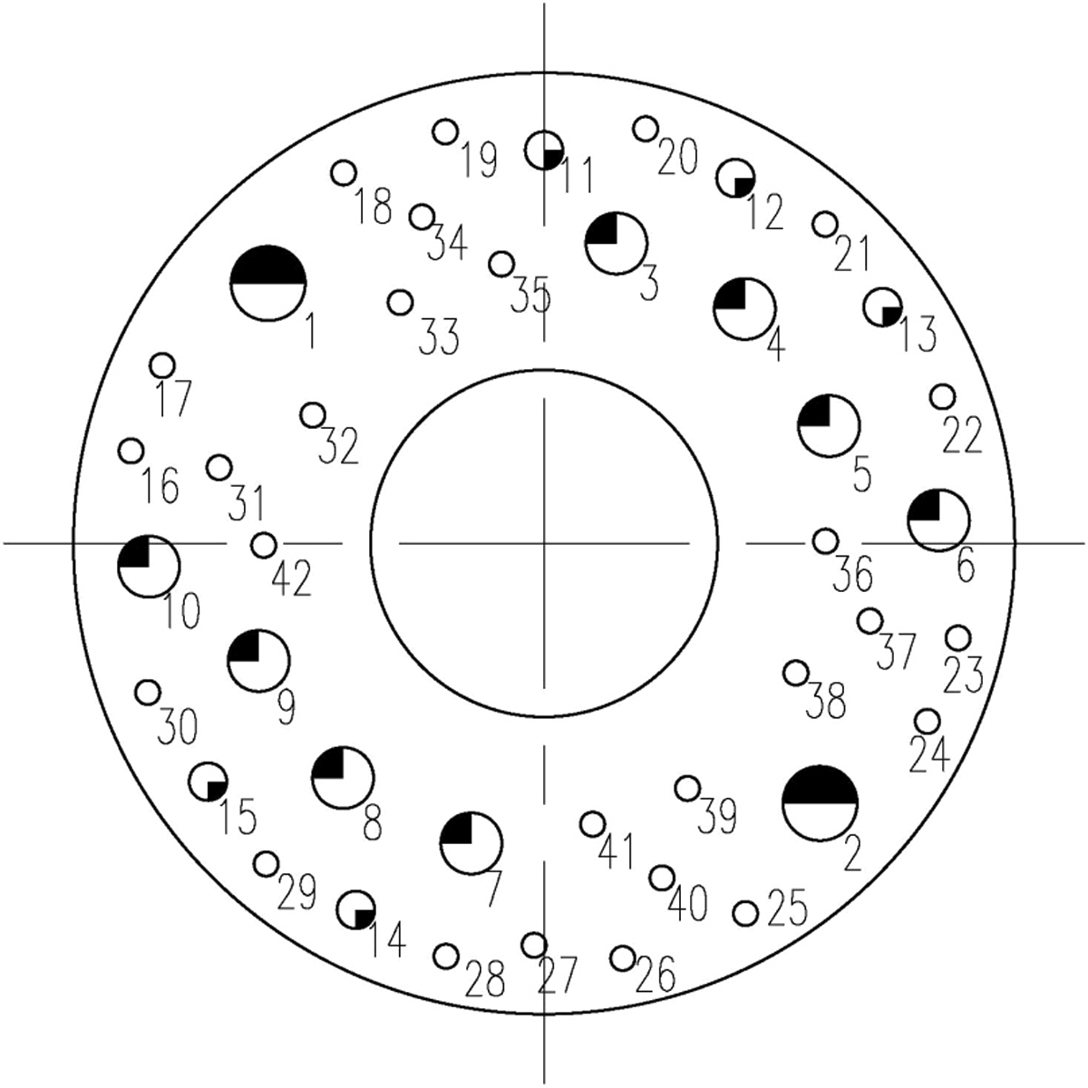
Note: The φ2.41 contact contains four 12 mm coaxial contacts.
Note: When multiple contacts are operating simultaneously, the rated current decline rate meets the requirements in the table below.
|
Number of Contacts |
1 ~ 10 | 11 ~ 20 | 21 ~ 30 | 31 ~ 50 | 51 ~ 80 | ≥81 |
| Decline Rate % | 0% | 10% | 20% | 30% | 40% |
50% |
Insulation Resistance
|
1 atm |
High Temperature | Humid and Heat | Rain Test |
| ≥3000 mΩ | ≥500 mΩ | ≥50 mΩ |
≥50 mΩ |
Dielectric Withstand Voltage
|
1 atm |
Humid and Heat | Low Pressure |
| AC 1000 Vrms | AC 500 Vrms |
AC 200 Vrms |
How to Order
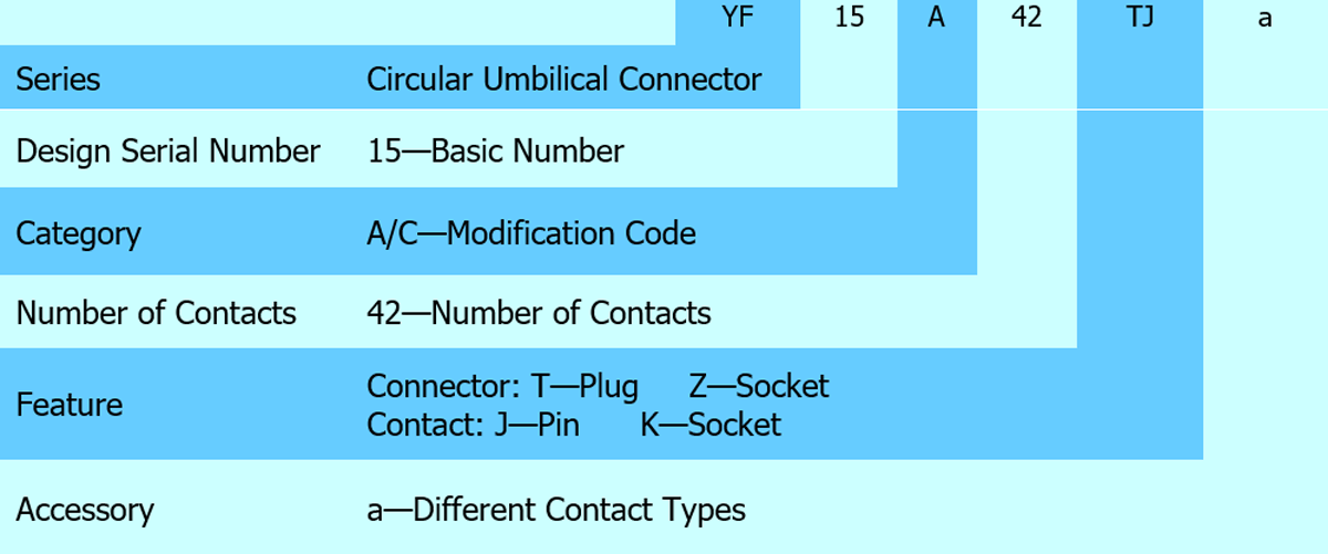
Connector Specification
|
Quality Grade |
Plug Type | Feature | Part Number of Socket | Feature |
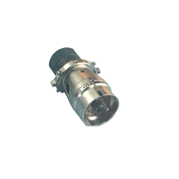
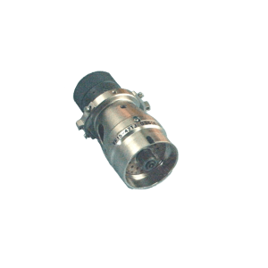
| J Grade | YF15-42TJ | Crimp
4 12#Coaxial Pin |
YF15-42ZK |
Crimp 4 12#Coaxial Pin |
|
YF15A-42TJ |
Solder Cup
Without locking Mechanism |
YF15A-42ZK | Solder Cup | |
| YF15A-42TJa | Solder Cup
Without Locking Mechanism, Guide Pin, Coaxial Pin, Simulated Air Needle |
YF15A-42ZKa |
Solder Cup With Guide Hole, Coaxial Socket, Simulated Air Hole |
|
|
YF15C-42TJ |
Crimp
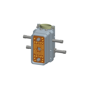
With Coaxial Pins, Composite Material Shell, Single Outlet |
YF15C-42ZK | Crimp
With Coaxial Socket, Composite Material Shell Non-Back shell |
|
| YF15C-42TJa | Crimp
Composite Material Shell, Single Outlet |
YF15C-42ZKa |
Crimp With Composite Material Shell Without Back shell |
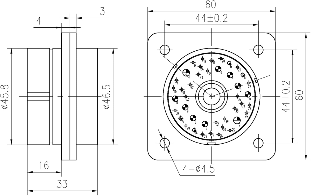
YF15-42 (Including YF15A/C-42) Contact Arrangement (Front View of Socket Mating Surface)
 |
|
Contact Type |
Symbol | Contact Specifications | Number Of Contacts | Contact Soldering Cup / Crimping | ||||
| YF15-42 | YF15A-42 | YF15C-42 | Inner Diameter | Section Area |
Solderable Area |
|||
|
Soldering Contact |
 |
Φ1.0mm | —— | 27 | —— | Φ1.4 mm | 1.54 mm2 | 1.08 mm2 |
 |
Φ1.6mm | —— | 5 | —— | Φ2.2 mm | 3.8 mm2 |
2.66 mm2 |
|
 |
Φ2.41mm | —— | 4 | —— | Φ3.2 mm | 8 mm2 | 5.6 mm2 | |
 |
Φ3.15mm | —— | 2 | —— | Φ4.4 mm | 15.2 mm2 |
10.64 mm2 |
|
|
Crimping Contact |
 |
Φ1.0mm | 27 | —— | 27 | Y38-0000-02/Y38-0000-07.00 | ||
 |
Φ1.6mm | 5 | —— | 5 |
JF11-77-24/JF11-77-36 |
|||
 |
Φ2.41mm | 4 | —— | 6 or 8 | Y38-0000-05/Y38-0000-10 | |||
 |
Φ3.15mm | 2 | —— | 2 |
JF11-77-22/JF11-77-35 |
|||
|
Coaxial Contact |
 |
12# | 4 | 0 or 2 | 2 or 0 | —— | ||
| End Cap |  |
12# | —— | 2 or 0 | —— |
—— |
||
|
Simulated Gas Path Contact |
 |
12# | —— | 1 (Contact 9) | —— |
—— |
||
Dimension
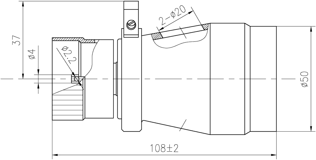
Plug YF15-42TJ
 |
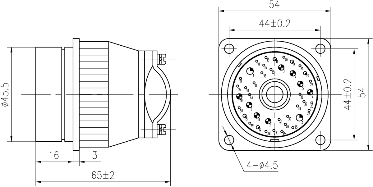
Socket YF15-42ZK
 |
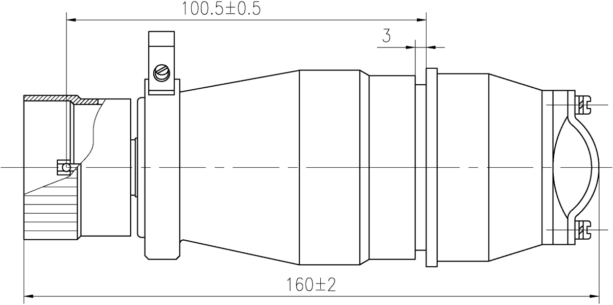
Plug/Socket YF15-42TJ/ZK
 |
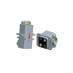
Sockets YF15A-42ZK, YF15A-42ZKa
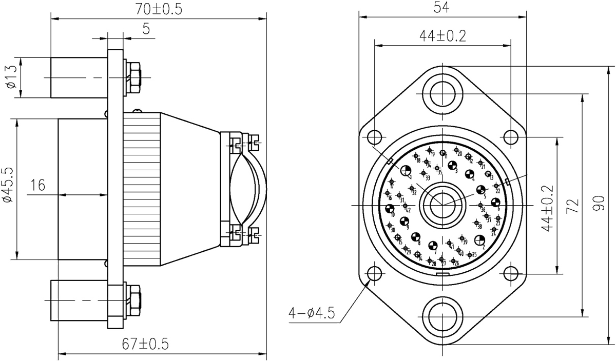 |
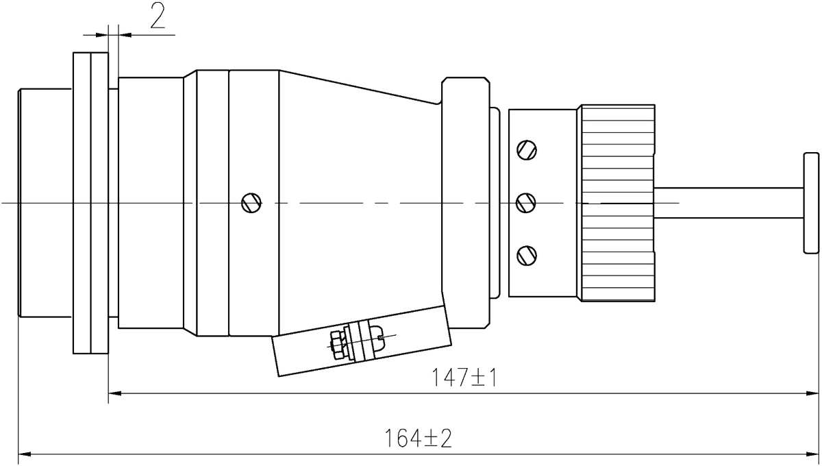
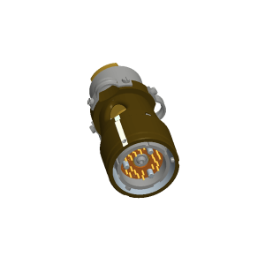
Plugs YF15A-42TJ and YF15A-42TJa
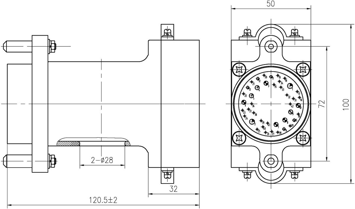 |
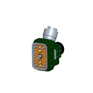
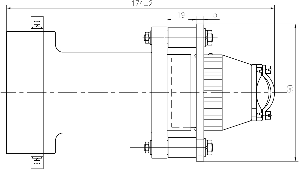
Plugs/Sockets YF15A-42TJ/ZK, YF15A-42TJa/ZKa
 |
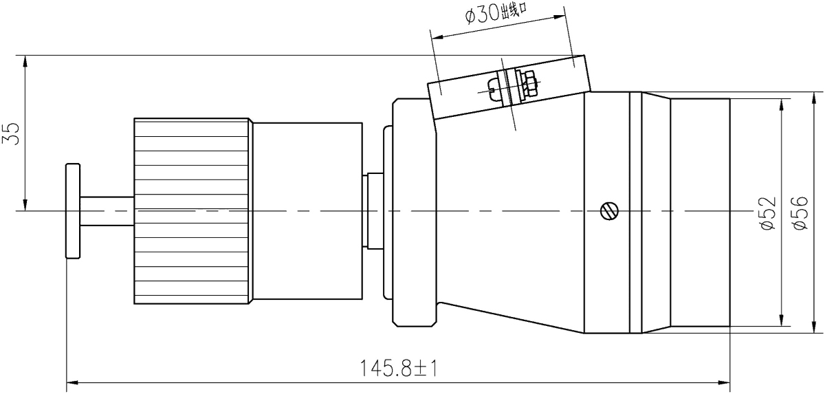
Plugs YF15C-42TJ and YF15C-42TJa
 |
Sockets YF15C-42ZK, YF15C-42ZKa
 |
Plugs/Sockets YF15C-42TJ/ZK, YF15C-42TJa/ZKa
|
|