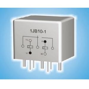
1JB10-1 Subminiature Magnetic Latching Relay
Environmental Characteristics
| No. | Parameter | Environmental Specification | |
| 1 | Quality Grade | Ⓙ, (G) | |
| IV | |||
| 2 | Temperature Range | (℃) | -55~+125 |
| 3 | Relative Humidity | (40±2) ℃, 90%~95% | |
| 4 | Low Pressure | (kPa) | 0.67~0.27 |
| 5 | Sinusoidal Vibration | (Hz) | 10~2000 |
| (m/s2) | 196 | ||
| 6 | Random Vibration | ((m/s2)2/Hz) | 20 |
| 7 | Shock | (m/s2) | 735 |
| 8 | Constant Acceleration | (m/s2) | 735 |
Main Characteristics
| Contact Arrangement | SPDT | Operating Time (ms) | ≤5 | ||
| Coil Power(W) | 1.1 | Release Time(ms) | – | ||
| Leak Rate (Pa.cm3/s) | ≤1×10⁻² | Load Ratings | Resistive | 10 A, 28 Vd.c. | |
| Contact Resistance (Ω) | Initial | ≤0.05 | Low Level | 10 µA~50 µA, 10 mV~50mV | |
| After Life | ≤0.1 | Life Time (Cycles) | 5×10⁴ | ||
| Insulation Resistance (MΩ) | Normal | ≥500(500 Vd.c.) | Overload Rating | Resistive 40A, 28 Vd.c. | |
| High Temp./Humidity | ≥10(500 Vd.c.) | ||||
| Dielectric Strength (50Hz) | Normal | 500 Vr.m.s | Weight(g) | ≤25 | |
| Low pressure | 200 Vr.m.s | ||||
Electrical Specification (Vd.c.)
| Specification No. | Coil Voltage | 25℃ | Overall Temperature Range | ||||
| Normal | Max | Coil resistance
(1±10%) Ω |
Operating Voltage
(max) |
Release Voltage
(min) |
Operating Voltage (max) | Release Voltage
(min) |
|
| 006 | 6 | 7.5 | 30 | 3.6 | — | 5.1 | — |
| 012 | 12 | 15 | 130 | 7.2 | — | 10.2 | — |
| 028 | 28 | 32 | 730 | 18 | — | 24 | — |
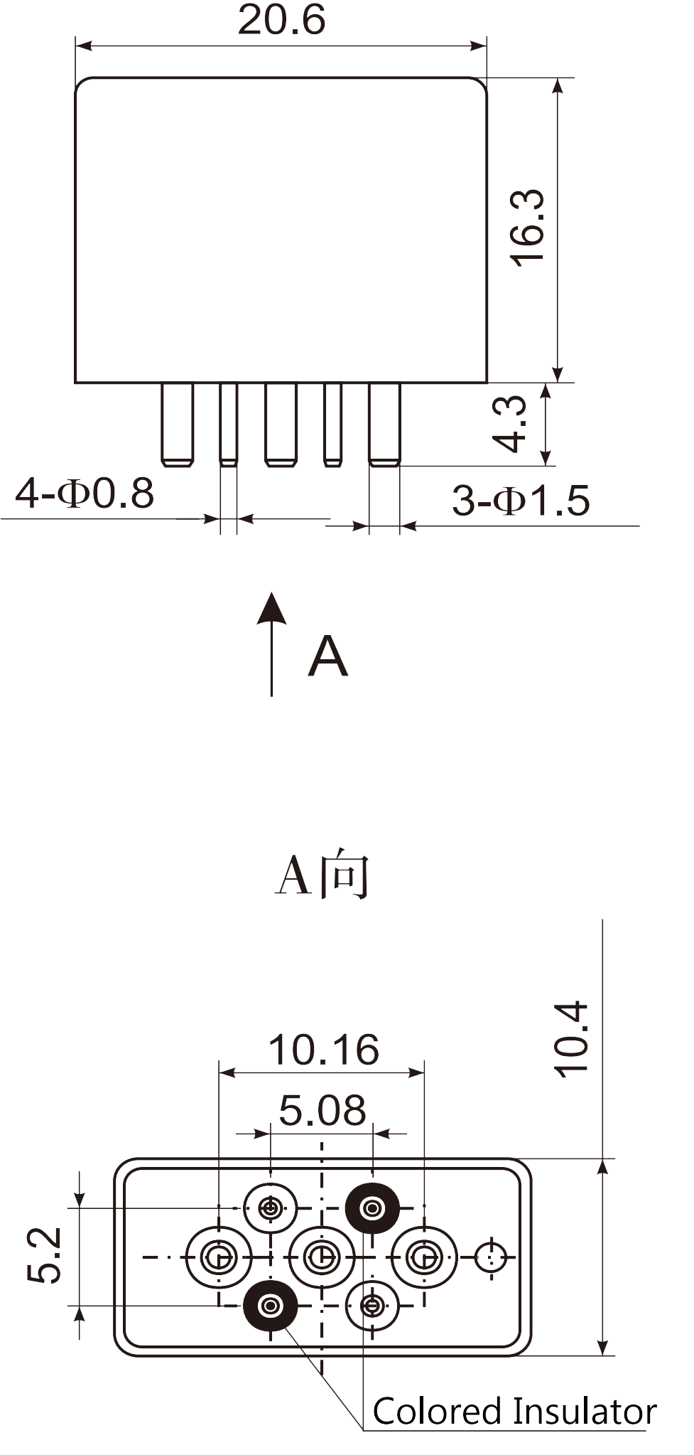
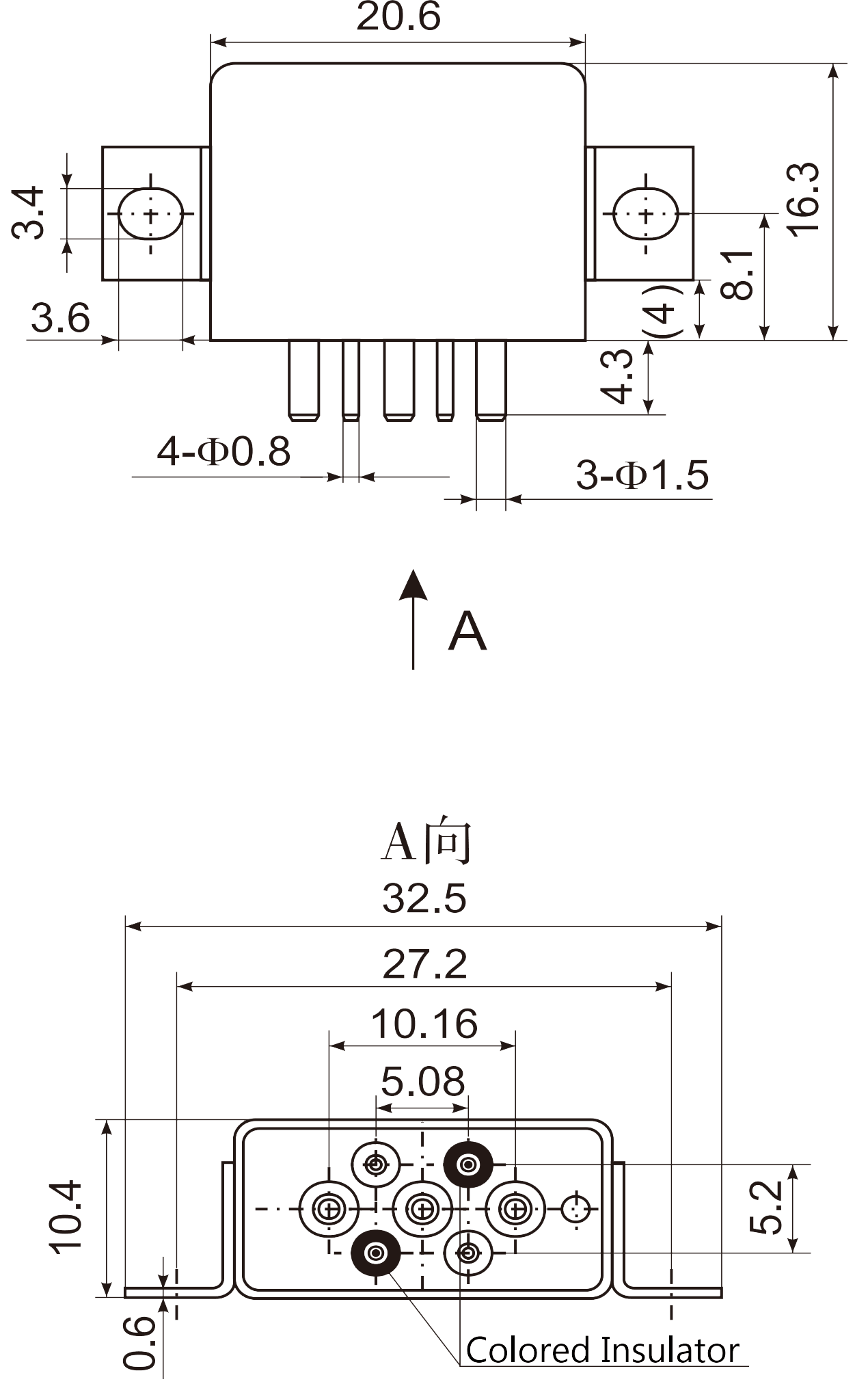
Dimensions |
||
 |
 |
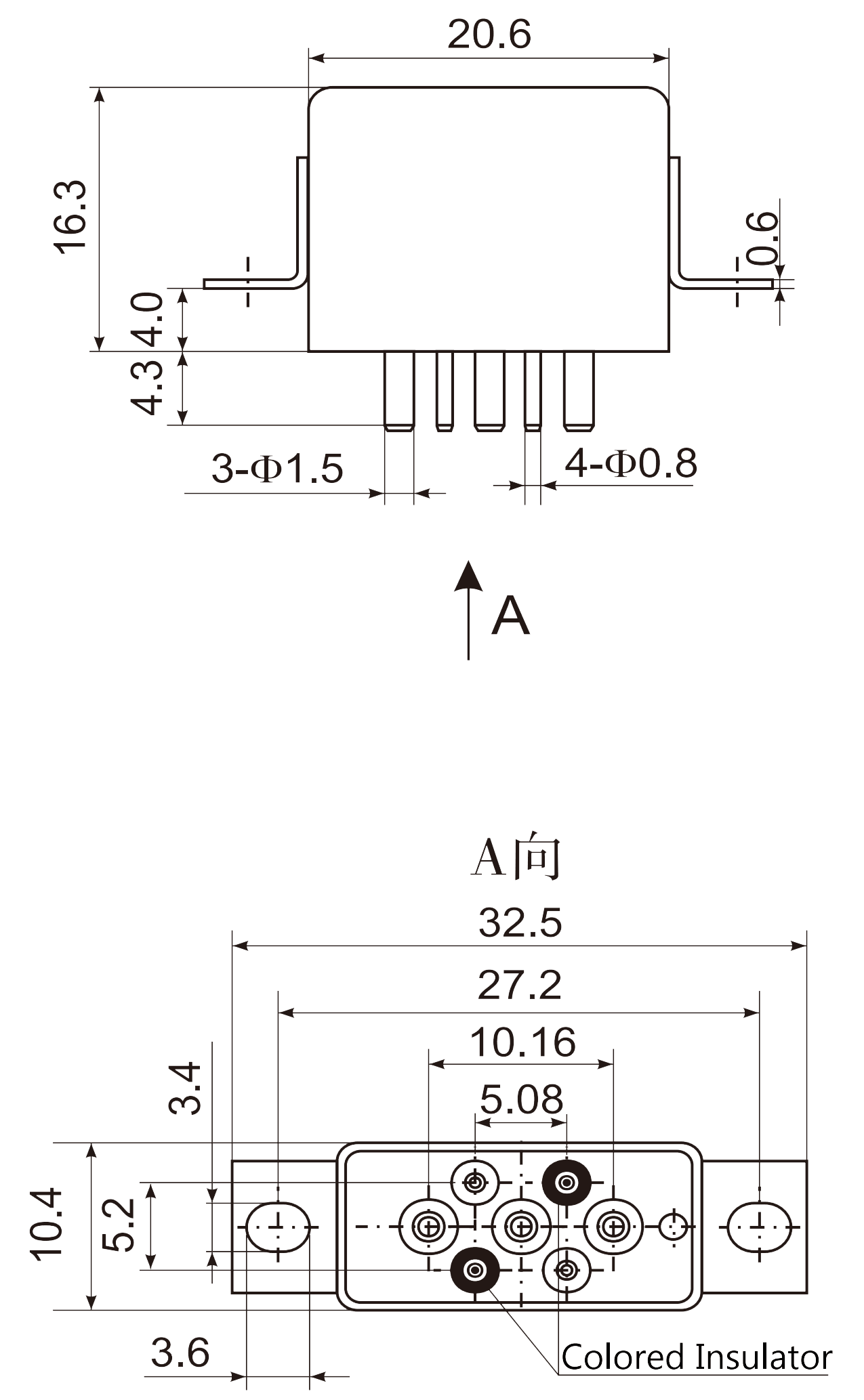 |
| Mounting Style: A (0) | Mounting Style: B (3) | Mounting Style: C (2) |
| Note: Vibration sensitive direction: Vertical | ||
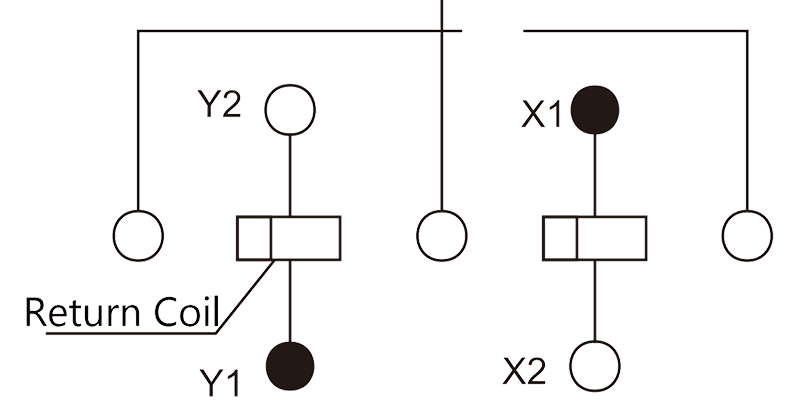
Circuit Diagram |
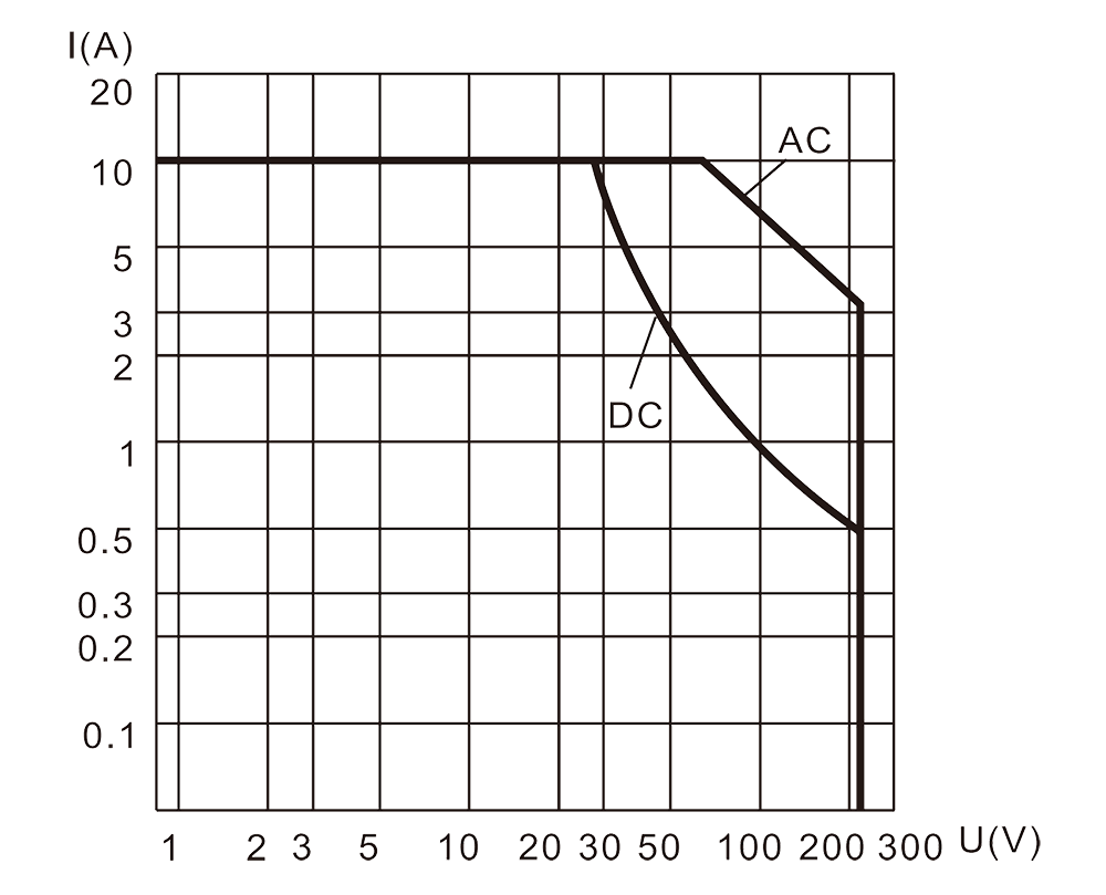
Resistive Load Diagram |
 |
 |
Order mark
Example: 1JB10-1 /IV 28 B
| 1JB10-1 | / | IV | 28 | B |
| Product number | Environmental rating | Coil voltage | Mounting style |
Detailed specification: RY4.536.029JT