Specifications
| Shell | Aluminum Alloy |
| Shell Finishing | Electroless Nickel Plating, covered with military green paint |
| Insulator | Thermoplastic Plastic |
| Sealing Ring | Silicone Rubber, Nitrile Rubber |
| Contact | Gold-Plated Copper Alloy
Ordinary Contacts (Solder Cup) Coaxial Contacts (Crimp) |
| Mechanical Life | 500 cycles |
| Electromagnetic Demating | 27 ± 3 V(DC) |
| Mechanical Dematng | 120 N ~ 200 N |
| Vibration | Sinusoidal Vibration: Frequency 10 ~ 2000Hz, Acceleration 200m/s²
Constant Frequency Vibration: Frequency 50Hz, 260Hz, Power Spectral Density 200m/s² |
| Shock | 1 ms Half-sine Wave
Peak Acceleration 1200 m/s² |
| Acceleration | Peak Acceleration 490 m/s² |
| Operating Temperature | -55℃ ~ +125℃ |
| Salt Spray Test | 48 h |
| Relative Humidity | At 40℃ ± 2℃: 92% ~ 98% |
| Rain Test | Rainfall Intensity 5 mm/min |
| Flameproof | The socket’s mating surface can withstand a high temperature of 2000℃ for 2 seconds |
| Air Tightness | The sealed socket can withstand 2MPa |
Electrical Ratings
Contact Resistance and Rated Current
|
Contact Specifications |
Contact Resistance mΩ | Rated Current | Characteristic Impedance | ||
| Single-layer | Sealing |
Triple-layer |
|||
|
Φ1.0mm |
≤ 7 mΩ | ≤ 7 mΩ | ≤ 20 mΩ | 5 A | —— |
|
Φ2.0mm |
≤ 5 mΩ | ≤ 5 mΩ | ≤ 15 mΩ | 20 A |
—— |
| Φ3.5mm | ≤ 3 mΩ | ≤ 3 mΩ | ≤ 10 mΩ | 40 A |
—— |
|
1553B |
Center, Intermediate Conductor ≤55 mΩ,Outer Conductor ≤6.25 mΩ | —— | 75 Ω | ||
| Ethernet | Inner Conductor ≤ 15 mΩ, Outer Conductor ≤ 3 mΩ | —— |
100 Ω |
||
|
12#Coaxial |
Inner Conductor ≤ 55 mΩ, Outer Conductor ≤ 6.25 mΩ | —— |
50 Ω |
||
Note: When multiple contacts are operating simultaneously, the rated current decline rate meets the requirements in the table below.
|
Number of Contacts |
1~10 | 11~20 | 21~30 | 31~50 | 51~80 | ≥81 |
| Decline Rate % | 0% | 10% | 20% | 30% | 40% |
50% |
|
Electrical Continuity between Shell |
≤5 mΩ | |||||
| Shielding |
Field strength 50,000 volts/meter Spectrum range less than 100MHz, minimum attenuation is 60dB |
|||||
Insulation Resistance
|
Normal Temperature |
High Temperature | Humid and Heat | Rain Test | |
| Contact | 1000 mΩ | 50 mΩ | 50 mΩ |
50 mΩ |
|
Electromagnetic Coil |
500 mΩ | 20 mΩ | 10 mΩ | 10 mΩ |
| Shielding |
Field strength 50,000 volts/meter Under the condition of spectral range less than 100MHz, minimum attenuation is 60dB |
|||
Dielectric Withstand Voltage
|
Normal Temperature |
High Temperature | Humid and Heat | Rain Test | Low Pressure | |
| Ordinary Contact | 1000 Vrms | 1000 Vrms | 250 Vrms | 250 Vrms |
200 Vrms |
|
1553B, Ethernet, RF Contacts |
500 Vrms | 200 Vrms | 200 Vrms | 100 Vrms | 100 Vrms |
| Electromagnetic Coil | 625 Vrms | 625 Vrms | 200 Vrms | 200 Vrms |
100 Vrms |
How to Order
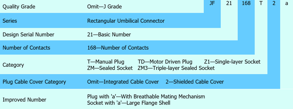
Connector Specifications
|
Quality Grade |
Plug Type | Feature | Part Number of Socket | Feature |
| J Grade | JF21-168T
JF21-168T2 JF21-168T2a JF21-168TD |
Manual Plug with Shielded Cable Cover
Manual Plug with Split Cable Cover Manual Plug with Split Cable Cover and Breathable Mating Mechanism Motor Driven Plug with Shielded Cable Cover |
JF21-168Z1
JF21-168ZM JF21-168ZM3 JF21-168ZM3a |
Single-layer Socket (Unsealed) Sealed Socket (Sealed) Triple-layer Sealed Socket (Sealed) Triple-layer Large Flange Socket (Sealed) |
Coaxial Contact Wire Lead
|
Code |
Wire Contact Type | Wire | Wire Length | Connection |
| JF21-168T
JF21-168T2 JF21-168T2a JF21-168TD JF21-168Z1 |
Without Wire Lead | —— | —— |
—— |
|
JF21-168ZM JF21-168ZM3 JF21-168ZM3a
|
1553B | TWSF/1553B-2
(White) |
3 m, 3 m, 1.8 m |
The white wire is connected to the central conductor (Positive Pole) The blue wire is connected to the middle conductor (Negative Terminal) Shielding layer connected to outer conductor |
|
12#Coaxial |
SFF-50-1.5-1 | 3 m, 3 m, 1.8 m | The wire is connected to the inner conductor
The shielding layer is connected to the outer conductor |
|
| 8#Coaxial | RCN8590 AWG24 | 3 m, 3 m, 1.8 m |
The wire is connected to the inner conductor The shielding layer is connected to the outer conductor |
|
|
JF21-168Z1(L=11m) JF21-168ZM3 JF21-168ZM3a
|
1553B | M17/176-0002 | 11 m, 3 m, 1.8 m | The white wire is connected to the center conductor
(Positive Pole) The blue wire is connected to the middle conductor (Negative Terminal) Shielding layer connected to outer conductor |
|
12#Coaxial |
SFF-50-1.5-1 | 11 m, 3 m, 1.8 m |
The wire is connected to the inner conductor The shielding layer is connected to the outer conductor |
|
| 8#Coaxial | ABS1503KD24 | 11 m, 3 m, 1.8 m |
The wire is connected to the inner conductor The shielding layer is connected to the outer conductor |
Coaxial Contact Accessories (Crimp)
|
Code |
Coaxial Contact Type | Contact | Adaptive Wires | Alternative Contacts | Adaptive Wires |
| JF21-168T
JF21-168T2 JF21-168T2a JF21-168TD |
1553B Socket | JF20-186-62 | TWSF/1553B-2 | JF20-186-64 |
TGSE 1553B-1 M17/176-0002 |
|
Ethernet Socket |
J599-0000-261 |
J599-0000-261a |
|||
|
12#Coaxial Socket |
JF20A-186-02 | SFF-50-1.5-1 |
JF20B-186-02 |
SFCF46-50-4-51 |
|
|
JF21-168Z1 |
1553B Pin | JF20-186-57 | TWSF/1553B-2 | JF20-186-58 | TGSE 1553B-1
M17/176-0002 |
|
Ethernet Pin |
J599-0000-161 | J599-0000-161a |
|
||
| 12#Coaxial Pin | JF20A-186-01 | SFF-50-1.5-1 | —— |
—— |
Note: Optional contact parts must be ordered separately.
Socket Backshells (Cable Cover)
|
Cable Cover Type |
Feature |
| JF21-168-41 |
Straight-outlet Shielded Cable Cover |
|
JF14-182-20 |
Angled-outlet Shielded Cable Cover |
| JF14-182-24 |
Angled-outlet Split Cable Cover |
Note: Cable covers are not included with the sockets at the factory. Users can choose according to their needs.For detailed dimensions of the cable cover JF14-182-20/24, please refer to the JF14 product sample page.
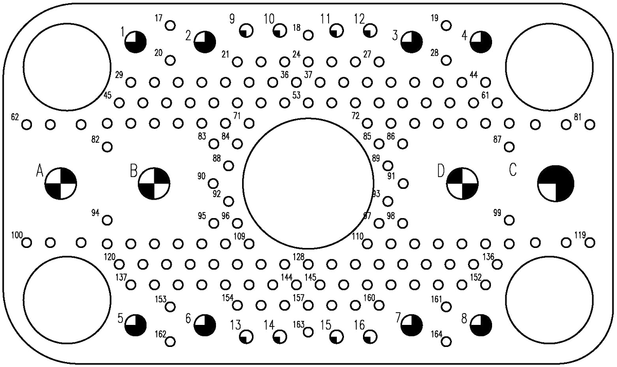
Contact Arrangement (Front View of Plug Mating Surface)
 |
|
Contact Type |
Symbol | Contact Specifications | Contact Number | Number of Contacts | Contact Soldering Cup Diameter |
|
Ordinary Contact |
 |
Φ1.0 mm | 17# ~ 164# | 168 | Φ1.5 mm |
 |
Φ2.0 mm | 9# ~ 16# | 8 |
Φ2.7 mm |
|
 |
Φ3.5 mm | 1# ~ 8# | 8 |
Φ4.5 mm |
|
|
Coaxial Contact (Distinguish between Plug and Socket) |
 |
1553B | A, B | 2 | —— |
 |
Ethernet | C | 1 |  |
|
 |
12#Coaxial | D | 1 |
—— |
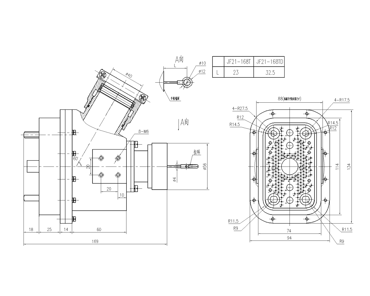
Dimension
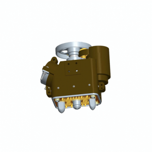
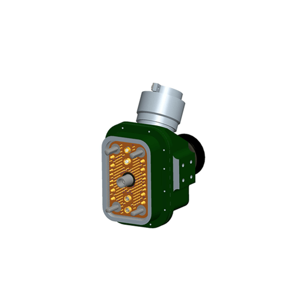
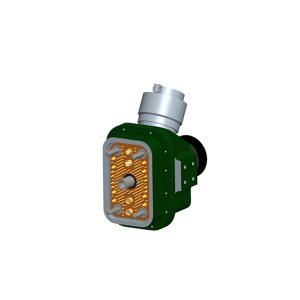
Plugs (JF21-186T, JF21-186TD)
 |
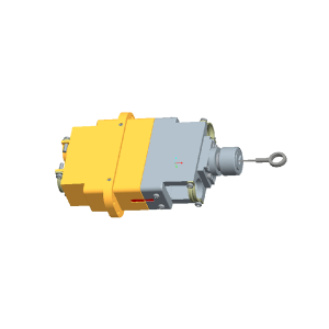
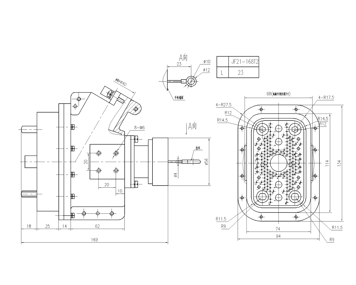
Plug (JF21-168T2)
 |
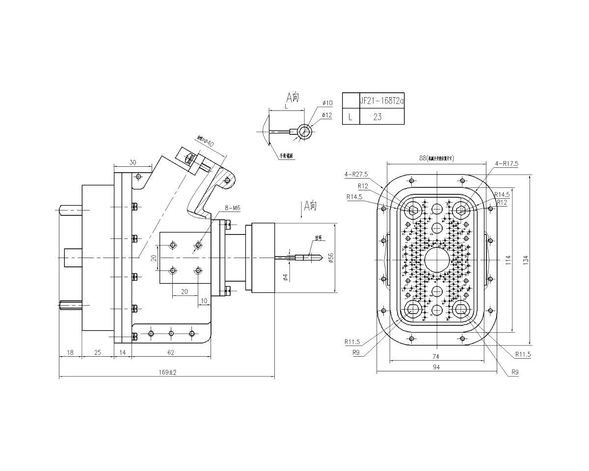
Plug (JF21-168T2a)
 |
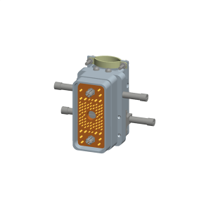
Socket (JF21-168Z1)
 |
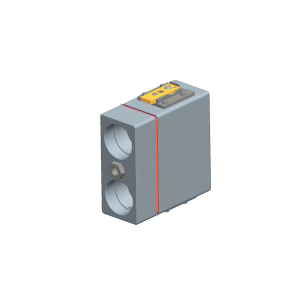
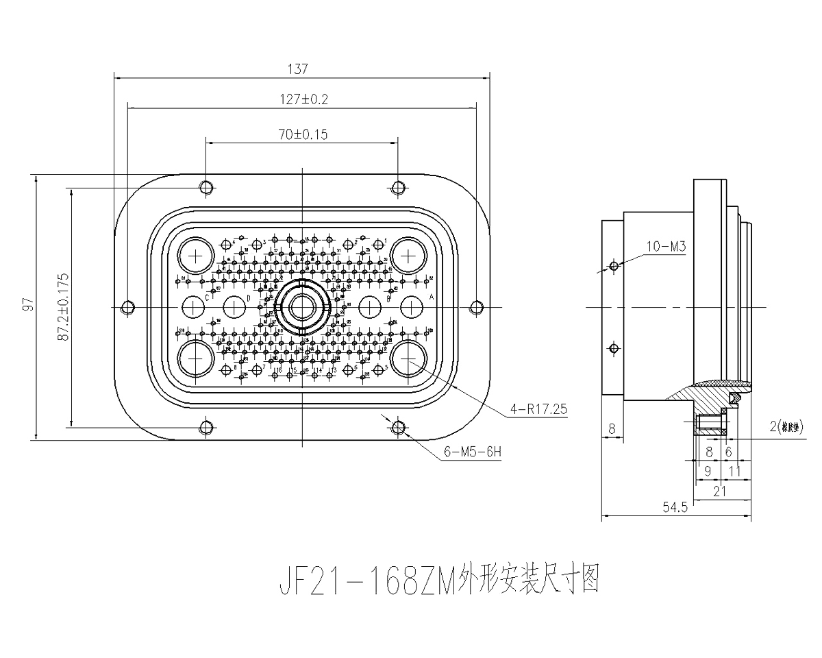
Socket (JF21-168ZM)
 |
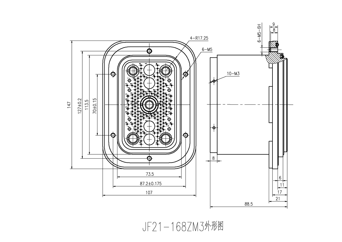
Socket (JF21-168ZM3)
 |
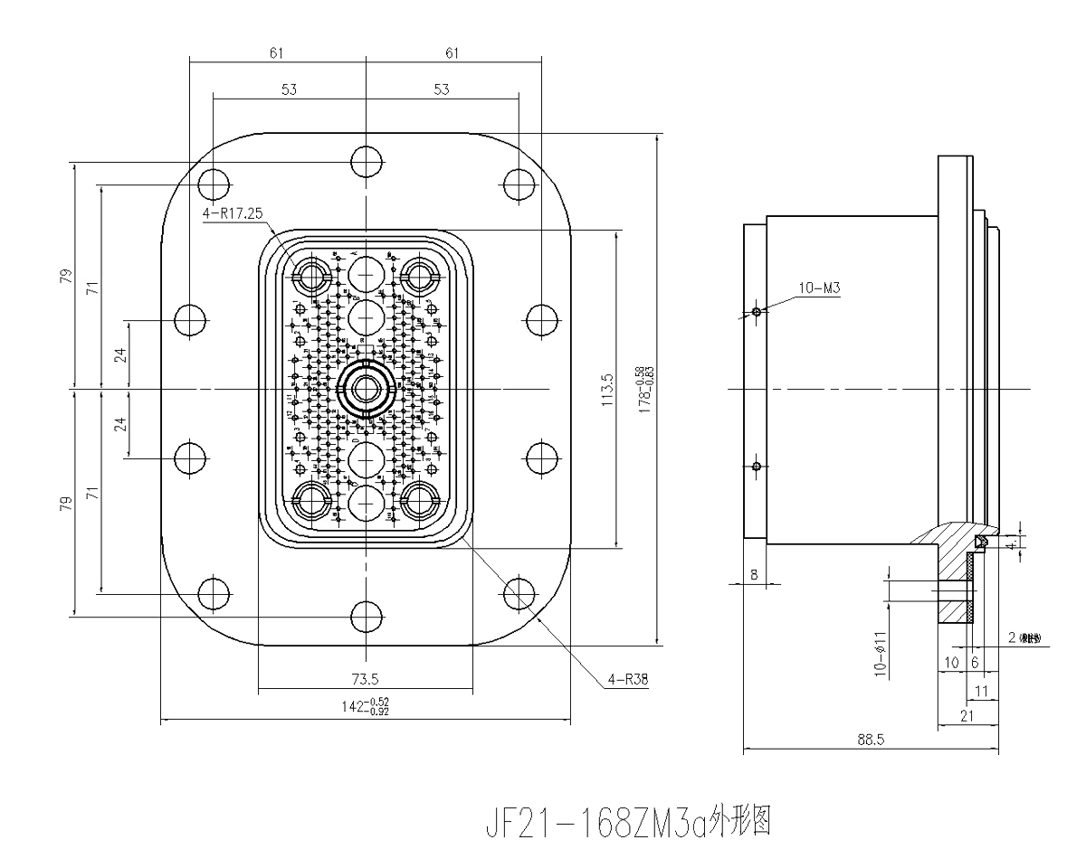
Socket (JF21-168ZMa)
 |
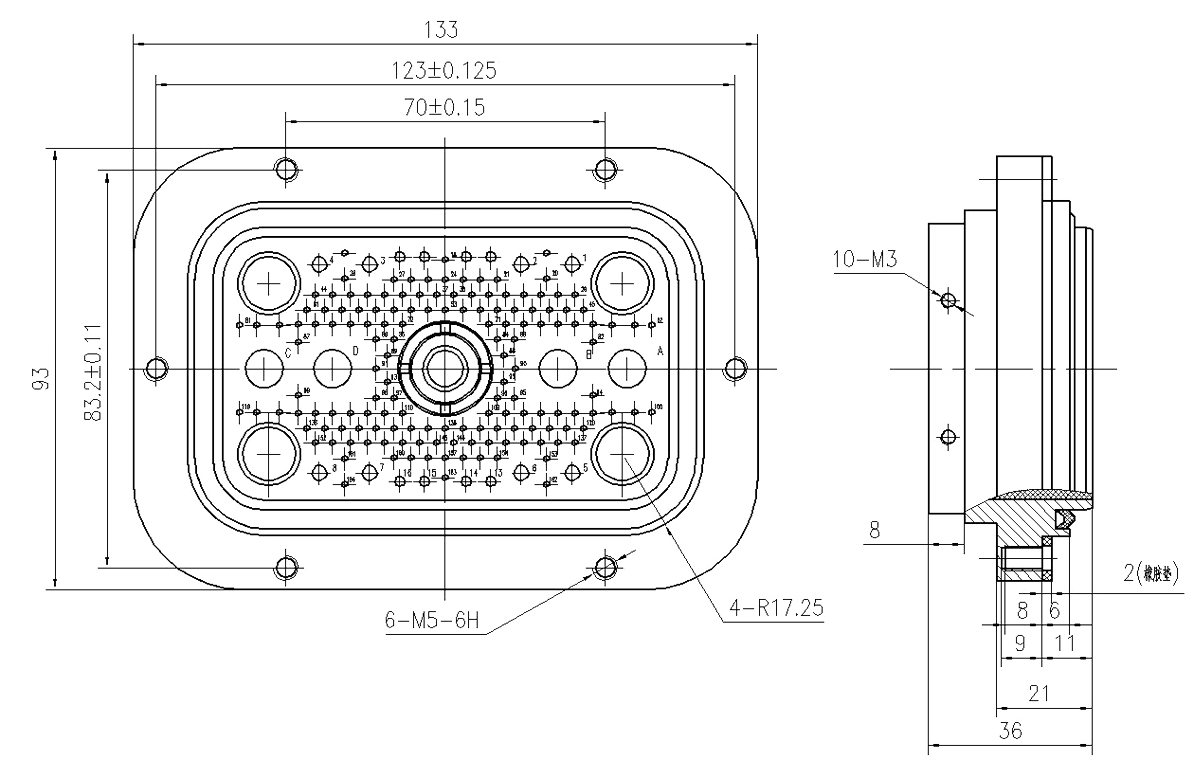
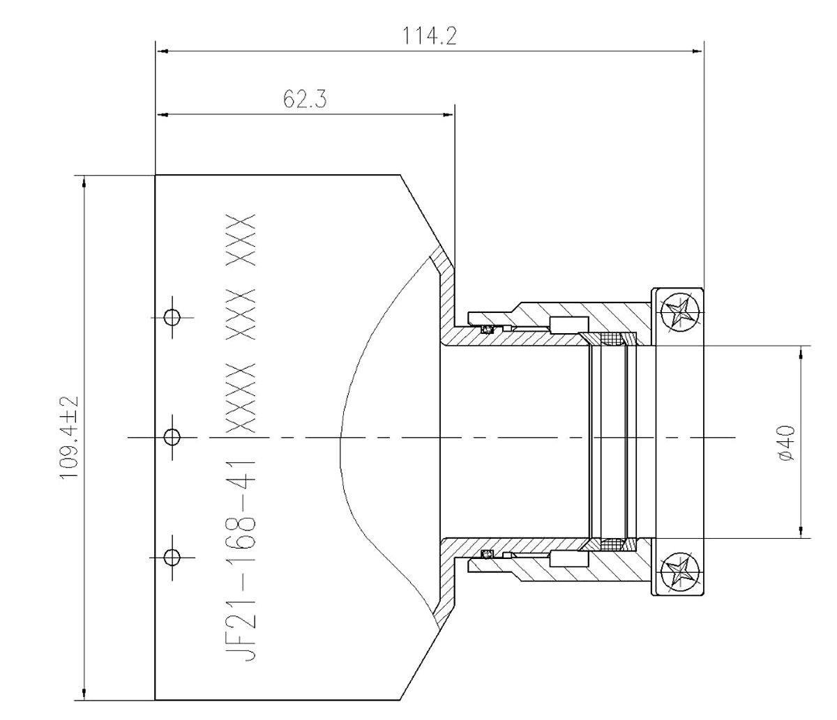
Socket Cable Cover (JF21-168-41)
 |