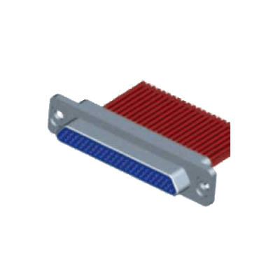
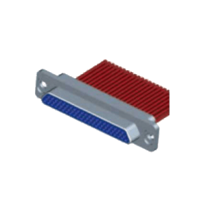
J29A Series Micro Rectangular Electrical Connector
Characteristic
- Operating temperature: – 55℃~+125℃
- Vibration: 10Hz ~2000Hz, 196m/s2
- Random Vibration: Power spectral density 0.6g2/Hz, RMS value of total acceleration: 28.4g
- Shock: 1200m/s2, 6ms
- Rated Currency: 5A
- Contact Resistance: ≤ 10mΩ
- Insulation Resistance: ≥ 5000MΩ
- Dielectric withstand Voltage: 1500V DC
- Life time: 500 cycles
- Hermetic Parameters (Only apply for J29M Series products):
Water seal: Differential pressure of one bar, no air bubble during inspection in water
Hermetic: 1×10⁻¹Pa.cm3/s (differential pressure of one bar)
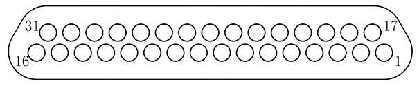
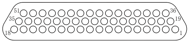
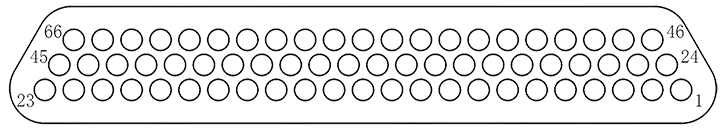
Contact arrangements
 |
 |
 |
 |
| J29A-9P | J29A-15P | J29A-21P | J29A-25P |
 |
 |
||
| J29A-31P | J29A-37P | ||
 |
 |
||
| J29A-51P | J29A-66P | ||
Product Family Tree
|
J29A Series |
||||||||||||
| J29A general | J29A-A | J29A-A1 |
J29M (Hermetic) |
|||||||||
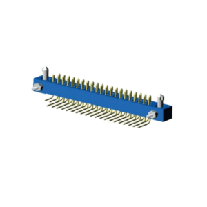
with crimp contacts |
with solder contacts |
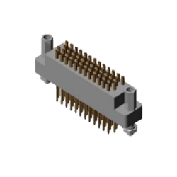
PCB with grid of 1.91×1.65 |
PCB with grid of 1.91×2.54 |
PCB with grid of 3.82×2.54 |
|
|
(PCB with grid of 1.91×2.54) |
(PCB with grid of 3.82×2.54) |
|
|
|
|
|
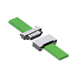
J29A Locking Subassemblies |
|
| Free Locking subassemblies(L, L1 — L4) |
End-fixed Locking subassemblies(P, P1~P16) |
According to the locking subassemblies, this series consists of end-free locking subassemblies and end-fixed locking subassemblies.
|
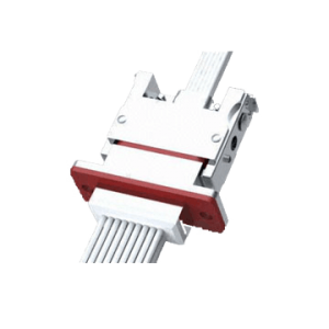
J29A Accessories |
||
With built-in cable clamp |
With no built-in cable clamp |
With built-in cable clamp |
Order Mark
- J29A series
| J29A | – | 25 | ZK | L4 | – | A1 | D2 | |||
Main code:
|
J29A | |||||||||
|
– | |||||||||
Number of contacts:
|
25 | |||||||||
Connector and Contact types:
|
ZK | |||||||||
Type of contact terminal:
|
– | |||||||||
| Locking devices types: see “J29A locking devices”.
Note: P3, P4, P6, P13, P15 are exclusive for J29A – XTJW/ZKW/TJWI/ZKWI |
L4 | |||||||||
Shell modification:
|
A1 | |||||||||
Accessory types:
|
D2 |
Note: Specific wire requirements are not part of the order information. Shall be presented the specifications of crimped wire in the brackets such as: Cross-sectional area of the wire, color and length, etc. If wiring relationship is complicated, the table of wiring shall be presented.
Example:
J29A – 25 ZK L4 – A1 D2 (Specific wire requirements)
The above mark means: a J29A connector with 25 contacts, socket with jacks, crimp terminal, Type L4 free locking subassemblies and D2 accessory.
- J29M series
| J29M | – | 51 | ZK | H | P5 | |
Basic series:
|
J29M | |||||
Number of Contacts:
|
51 | |||||
Connector and Contact types:
|
ZK | |||||
Contact termination type:
|
H | |||||
Locking devices type:
|
P5 |
Example:
J29M – 51 ZK H-P5 (Specific wire requirements)
The above mark means: a J29M connector with 51 contacts, socket with jacks, solder terminal, Type P5 fix-end locking subassemblies.