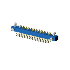
J27A Series Printed Circuit Board Electronic Connectors
Characteristic
|
Ambient temperature |
Grade I | -55°C~ +100°C | Relative Humidity | +40℃, 98% |
|
Grade II |
-55°C~ +125°C | Low air pressure | 0.3 kPa | |
|
Grade III |
-55°C~ +175°C | Shock |
1000 m/s2, 11ms |
|
| Rated current | 3A | Insulation resistance |
≥ 5000MΩ |
|
| Dielectric withstand voltage | 1000 V | Vibration |
10Hz ~ 2000Hz 150 m/s2 |
|
| Mechanical life | 1000 times | |||
Contact arrangement |
|
 |
 |
| J27A-17P | J27A-29P |
 |
 |
| J27A-41P | J27A-53P |
 |
|
| J27A-65P | |
 |
|
| J27A-72P | |
 |
|
| J27A-84P | |
 |
|
| J27A-96P | |
Product Family Tree
|
Accessory |
|||||||||||
|
Plug accessory |
Socket accessory |
||||||||||
|
T |
TX | TL | TD | TM | TF | Z | ZX | ZL | ZD | ZM |
ZF |
| Base | |||||||||||||
| Base with pins | Base with jacks | ||||||||||||
| 17 pins | 29 pins | 41 pins | 53 pins | 72 pins | 84 pins | 96 pins | 17 jacks | 29 jacks | 41 jacks | 53 jacks | 72 jacks | 84 jacks | 96 jacks |
Description:
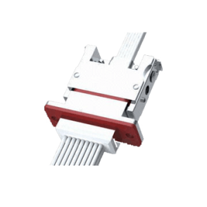
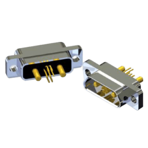
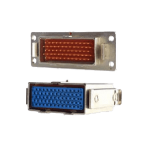
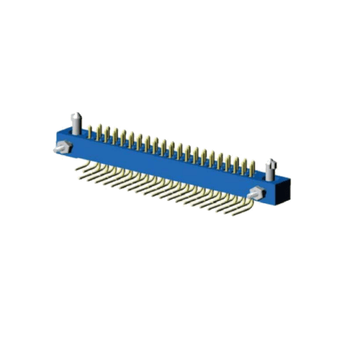
- This series of printed circuit connectors are divided into plugs and sockets. The end of the connector is divided into Straight insert in PCB, Right angle insert in PCB, Soldered and crimped. The wire section area is from 0.15mm2 to 0.25mm2.
- A connector with a male locking member is defined as a plug, and a connector with a female locking member is defined as a socket, i.e. the plug or socket is defined by the accessory fitting.
Order mark
| J27A | – | 41 | Z | K | L | II | BC | – | 0.8 | ||
Main code:
|
J27A | ||||||||||
Number of contacts:
|
41 | ||||||||||
Connector type:
|
Z | ||||||||||
Contact type:
|
K | ||||||||||
|
– | ||||||||||
Locking form:
|
L | ||||||||||
Environmental rating:
|
– | ||||||||||
End termination form:
|
BC | ||||||||||
Printed board aperture:
|
0.8 |
Note: additional instructions are not part of the order mark. In the case of selecting the crimp wire type product, please indicate the wire specifications of the crimped wire in the brackets such as the wire cross-sectional area, length and color. When the wiring specification is complicated, the wiring specification table shall be presented.
Example:
J27A – 41 ZKL II BC-0.8 (Additional Notes)
The above marks indicate that the number of contacts is 41, the connector type is socket with jacks, the locking type is thread locking, the environmental grade is II, the tail end is in the form of straight insert in printed board, and the printed board aperture is φ0.8.