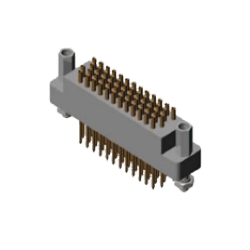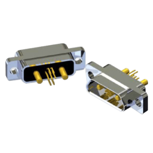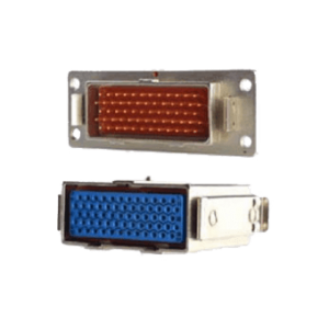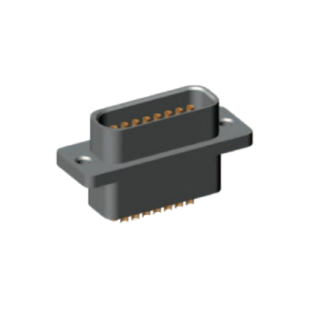
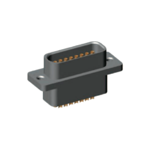
J40 Series Miniature Rectangle Electronic Connector
Characteristic
|
Rated voltage |
60 VD.C. | Rated current | 5A |
|
Contact resistance |
≤ 10mΩ | Insulation resistance | ≥ 1000MΩ |
|
Dielectric withstand voltage |
1000 V | Mechanical life | 500 times |
| Ambient temperature | -55°C~ +125°C | Vibration |
10Hz ~ 2000Hz 150 m/s2 |
| Random vibration | Power spectral density 0.4 g2/Hz,
Total acceleration rms value 23.1g |
Shock |
750 m/s2, 6ms |
| Acceleration | 500 m/s2 | Low air pressure |
0.3 kPa |
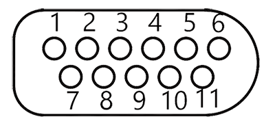
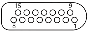
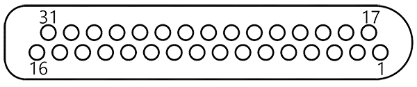
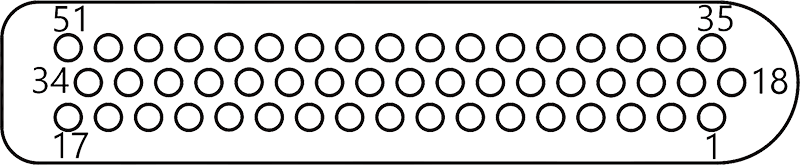
Contact arrangement
 |
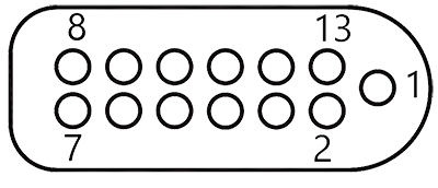 |
| J40-11 | J40-13 |
 |
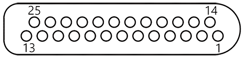 |
| J40-15 | J40-25 |
 |
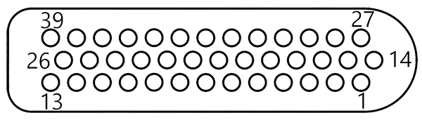 |
| J40-31 | J40-39 |
 |
|
| J40-51 | |
Product Family Tree
| Plug and Socket | ||||||||
| Normal | Improved | |||||||
|
Crimp |
(the outer shell doesn’t have flange in the width direction) |
(socket with sealing feature) |
(product plug with 90° clamp and locking screws, socket only with decorative plating, rubber mat and install screws socket is suitable for installation of 3 mm thickness plate after installation) |
(currently only 11 and 13 contacts) |
(currently only 39 contacts) |
(products except the through holes of two <t> 2.2, the same shape as TJ/ZK) |
(the crimping wire 22 core is 0.10mm~0.15mm, the shape is the same as TJ/ZK type) |
|
Locking device |
|||
| 11,13 pins |
15~51 pins |
||
K (fixed end) |
Q, Q1 (free end) |
P, P2 (fixed end) |
L, L2 (free end) |
Order mark
| J40 | – | 25 | ZK | S | P | – | () | |
Main code:
|
J40 | |||||||
Number of contacts:
|
25 | |||||||
|
ZK | |||||||
Indicates the tail form:
|
S | |||||||
Locking type:
|
P | |||||||
Improved:
|
– |
Note: additional instructions are not part of the order mark. In the case of selecting the crimp wire type product, please indicate the wire specifications of the crimped wire in the brackets such as the wire cross-sectional area, length and color. When the wiring specification is complicated, the wiring specification table shall be presented.
Example: J40 – 25 ZKS P (Additional Notes)
The above marks indicate that the number of contacts is 25 and socket jack type, the end of the contact is changed to the wire type, and the P-type mounting screw is used. (Additional note: wire cross-sectional area, length and color, etc.)