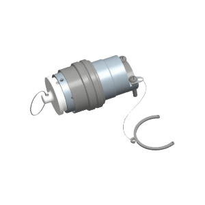
Y3 series Circular Hermetic Electrical Connector
Environmental Specifications
| Operating temperature | -55 to +125°C | Sinusoidal Vibration | 50 Hz ~ 2000 Hz, 196 m/s2 |
| Relative humidity | 95% at 40°C | Shock |
980 m/s2 1200 m/s2 (Y3-24TK/ZJLM) |
| Constant acceleration | 980 m/s2 | ||
| Working pressure | 101.3kPa ~ 6.67kPa | Mechanical life | 500 cycles |
Electrical specifications
- Contact resistance and rated current
|
Contact size (mm) |
Contact resistance (mΩ) | Rated Current (A) | |
| Normal seal | Glass sintering | ||
| Φ0.8 | ≤ 10 | ≤ 15 | 3 |
| Φ1.0 | ≤ 5 | ≤ 10 | 5 |
- Rated voltage, withstand voltage and insulation resistance
| Working Environment | Withstand Voltage (Vrms) | Insulation Resistance (MΩ) |
| Normal Temperature and pressure | 500 | ≥ 500 |
| High humidity | — | ≥ 20 |
| High temperature | — | ≥ 100 |
| Low air pressure: 4.39kpa | 200 | — |
- Mechanical specifications
| Housing Material | Aluminum alloy, stainless steel | Insulator Material | Thermoplastic |
| Housing Plating | Electroless Nickel plating | Contact plating | Gold plating |
Order mark
| Y3 | -19 | Z | J | B | M | |
Series No.
|
Y3 | |||||
Contact number
|
19 | |||||
connector type
|
Z | |||||
Contact type
|
J | |||||
Receptacle mounting type
|
B | |||||
Receptacle sealing type
|
M |
Note: Mounting type and Sealing type are only for receptacles, Plugs don’t have these two signs.
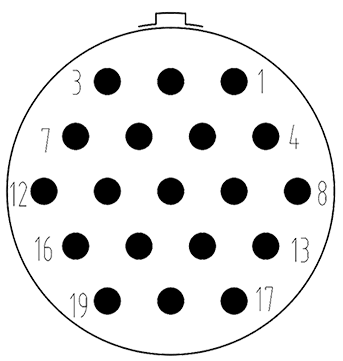
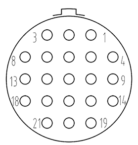
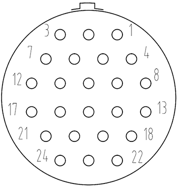
Contact arrangement
| Pin dia | 1 | 0.8 |
| Sign |  |
 |
 |
 |
 |
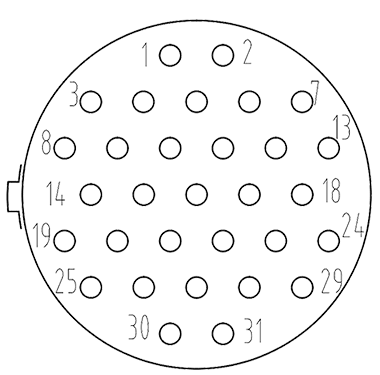 |
| 19-Φ1 | 21-Φ0.8 | 24-Φ0.8 | 31-Φ0.8 |
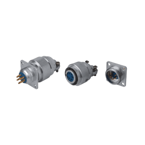
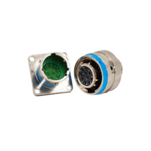
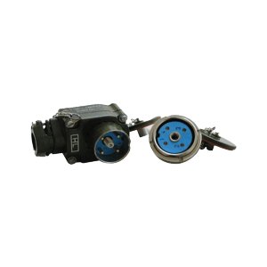
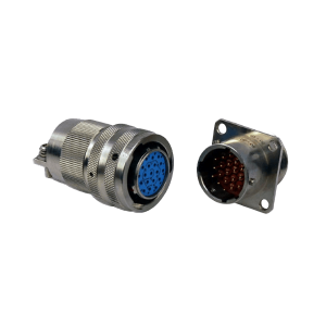
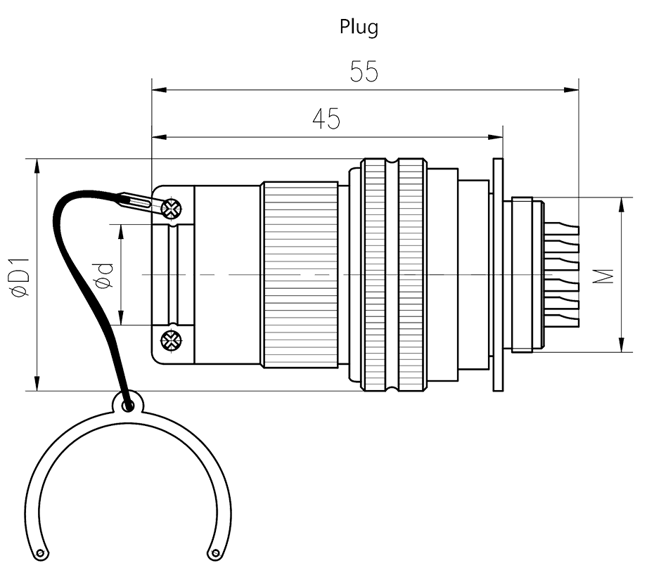
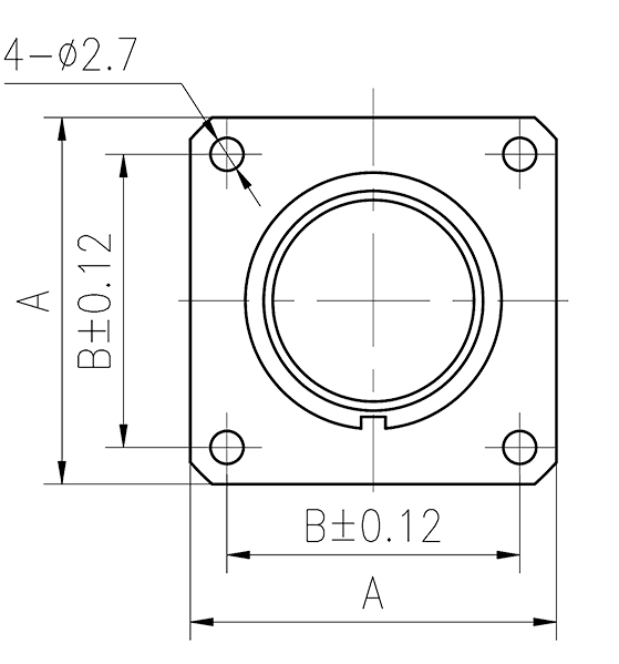
Drawings
 |
 |
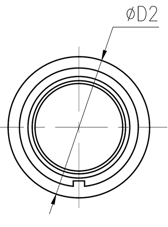 |
| Rectangular flange receptacle | Circular Flange receptacle |
| Part No. | A | B | øC | M | øD |
| Y3-19TK | — | — | — | — | 13 |
| Y3-19ZJLM | 30 | 24 | — | 20×0.75 | 13 |
| Y3-19ZJBM | 30 | 24 | — | 20×0.75 | — |
| Y3-19ZJHLM | — | — | 30 | 20×0.75 | 13 |
| Y3-19ZJHM | — | — | 30 | 20×0.75 | — |
| Y3-19ZJHR | — | — | 28 | — | — |
| Y3-19ZJHR11 | — | — | 25 | — | — |
| Y3-21T(T2) | — | — | — | — | 10(6.5) |
| Y3-21ZJBM | 26 | 20 | — | 16×1 | — |
| Y3-21ZJHM | — | — | 25 | 16×1 | — |
| Y3-21ZJHM11 | — | — | 21 | 16×1 | — |
| Y3-24TK | — | — | — | — | 13 |
| Y3-24ZJLM | 30 | 24 | — | 20×0.75 | 13 |
| Y3-24ZJBM | 30 | 24 | — | 20×0.75 | — |
| Y3-24ZJHR | — | — | 28 | — | — |
| Y3-24ZJHR11 | — | — | 25 | — | — |
| Y3-24ZJLR(BR) | 30 | 24 | — | 20×0.75 | (13) |
| Y3-31TK | — | — | — | — | 13 |
| Y3-31ZJLM | 30 | 24 | — | 20×0.75 | 13 |
| Y3-31ZJBM | 30 | 24 | — | 20×0.75 | — |
| Y3-31ZJHLM | — | — | 30 | 20×0.75 | 13 |
| Y3-31ZJHM | — | — | 30 | 20×0.75 | — |
| Y3-31ZJHR | — | — | 24.5 | — | — |
Operation Instruction
- The two parts of the electrical connector plug and receptacle are connected by straight plug, which is separated by direct dialing. After the head base is inserted, the anti-loose ring is inserted; if necessary, the fuse can be fixed on the anti-loose ring.
- When soldering the contacts, pay attention to the contact number. The power of the soldering iron used should be preferably not more than 45W, and the soldering time of the single contact should not be more than 5s.
- When the electrical connector needs to be cleaned, anhydrous ethanol should be used. The use of polar solvents such as acetone or banana water for cleaning is strictly prohibited.
- The electrical connector is forbidden to be energized before it is locked. In the case of load, separation is prohibited.
- When connecting the electrical connector, care should be taken to avoid loosening of the tail cover and damage to the cable core.
- When the electrical connector head and the seat are separated, cover the dust cover separately.
- After the wire is soldered, the cable cover of the cable cover must be clamped and fixed. If it is to be used in the open air for a long time, the right end of the cable cover should be sealed with a suitable seal.