GJB599 series Electrical Connectors
Product name code comparison table
|
Series |
I, II Series | III, IV series |
|
National military standard GJB599A main code |
JY |
J599 |
| US military standard MIL-DTL-38999 main code | MS |
D38999 |
Note: GJB599 series connector product model is the same as GJB599A; also, the same as MIL-DTL-38999 except for the main code.
GJB599 series environment-resistant quick separation, high density and small circular electrical connector intended use:
- GJB599 Series I: Generally suitable for systems that require quick separation in blind vision situations. These series of connectors are resistant to high-intensity vibrations and are suitable for use in harsh wind sands and moist environments when matched with suitable accessories.
- GJB599 Series II: This series of connectors is lighter in weight and smaller in size. It is generally suitable for applications that do not withstand high-intensity vibrations or weather and moisture. Suitable for use in tight spaces.
- GJB599 Series III: Generally suitable for systems that require quick separation in blind vision situations. These series of connectors are resistant to high-intensity vibrations and are suitable for use in harsh wind sands and moist environments when matched with suitable accessories.
- GJB599 Series IV: Generally suitable for systems requiring rapid separation and connection in blind vision situations. This series of connectors has the characteristics of high temperature resistance to high-strength vibration, suitable for places with small rotating space, and can be suitable for harsh wind sand and humid environment when matched with suitable accessories.
Product structure introduction
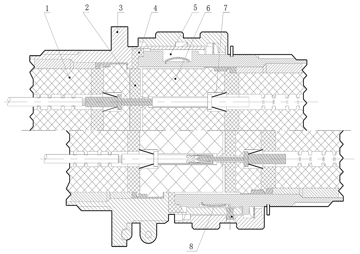
- Sealing body: Protect the wires from external liquids, dust, etc. into the product.
- Interface gasket: Each plugged contact is sealed.
- Receptacle housing: The pins can be protected under blind insertion conditions.
- Sealing ring: to achieve sealing of the butt interface.
- Five key bits on the housing: ensure accurate alignment of the contacts during mating.
- Socket insulation mounting plate: Enclosed at the entrance to protect the mating of the contacts.
- Reed ring: ensure reliable fixing of the contacts.
- Shielded reed: Ensures that the electrical conductivity between the housings is formed before the contacts are inserted.
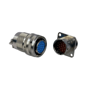
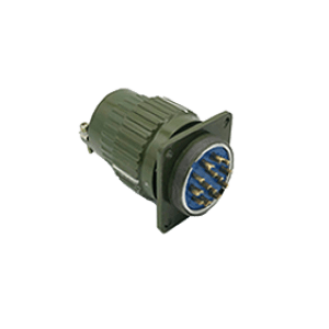
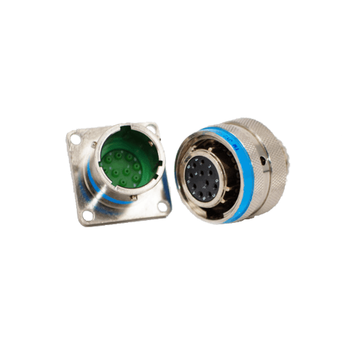
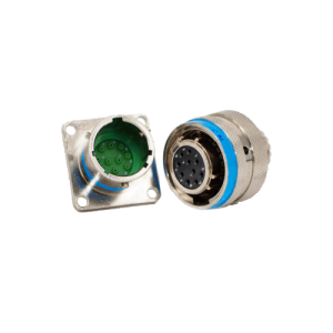
GJB599 I Series Product Overview
- Bayonet coupling system for quick locking and separation
- Scoop proof plug, protect the contacts under blind insertion conditions
- Primary key / keyway positioning error proof insertion
- EMI/RFI shielding and housing conductivity
- Excellent shock and vibration resistance
- Good liquid impregnation performance
Widely used in aviation, aerospace and military systems. With suitable accessories, it can be used in harsh wind and humid environments.
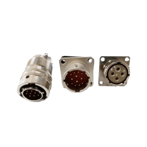
Primary key / keyway positioning
Positioning is determined by the primary key/keyway, and the remaining subkeys/keyway positions are unchanged.
- View of the socket of mating
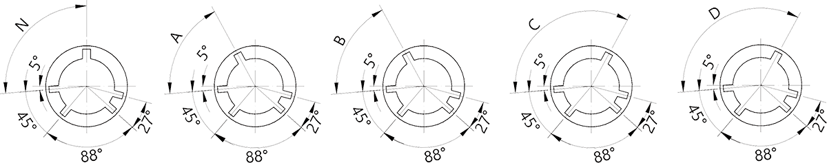
- View of the plug of mating
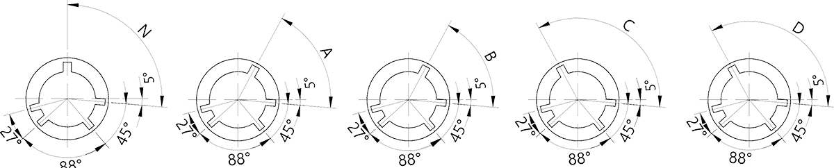
| Shell No. | Angle in degrees (° ) | ||||
| N | A | B | C | D | |
| 09 | 95 | 77 | — | — | 113 |
| 11 | 95 | 81 | 67 | 123 | 109 |
| 13 | 95 | 75 | 63 | 127 | 115 |
| 15 | 95 | 74 | 61 | 129 | 116 |
| 17 | 95 | 77 | 65 | 125 | 113 |
| 19 | 95 | 77 | 65 | 125 | 113 |
| 21 | 95 | 77 | 65 | 125 | 113 |
| 23 | 95 | 80 | 69 | 121 | 110 |
| 25 | 95 | 80 | 69 | 121 | 110 |
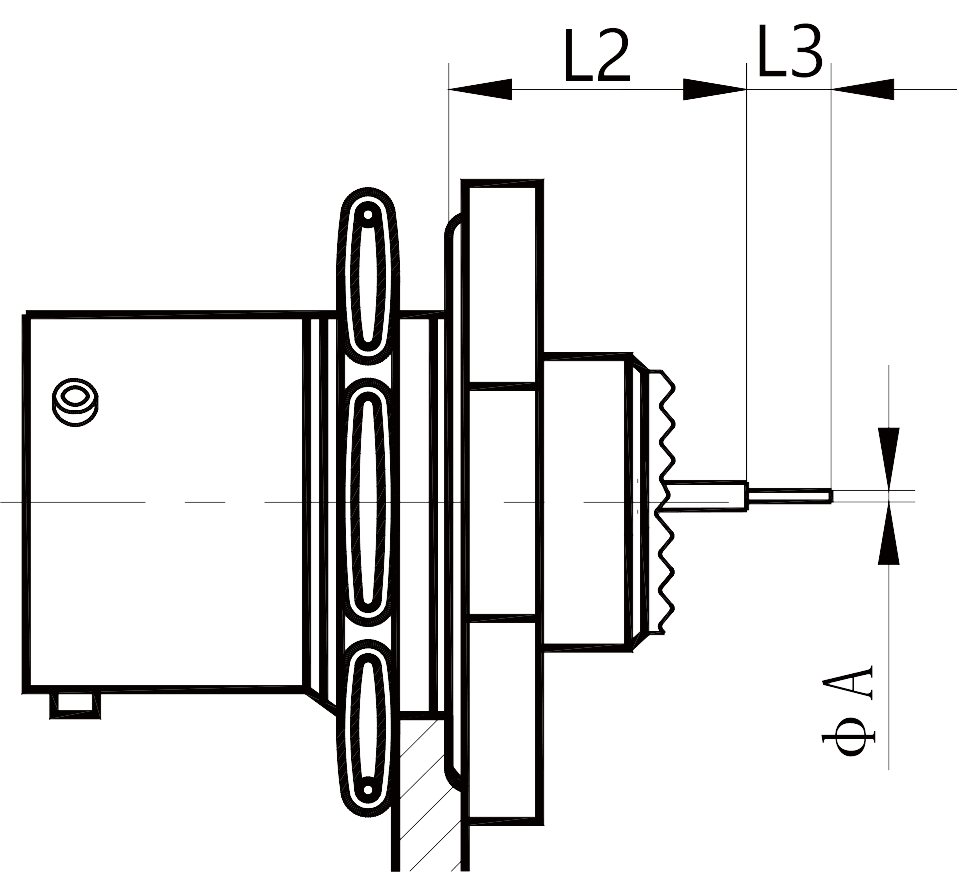
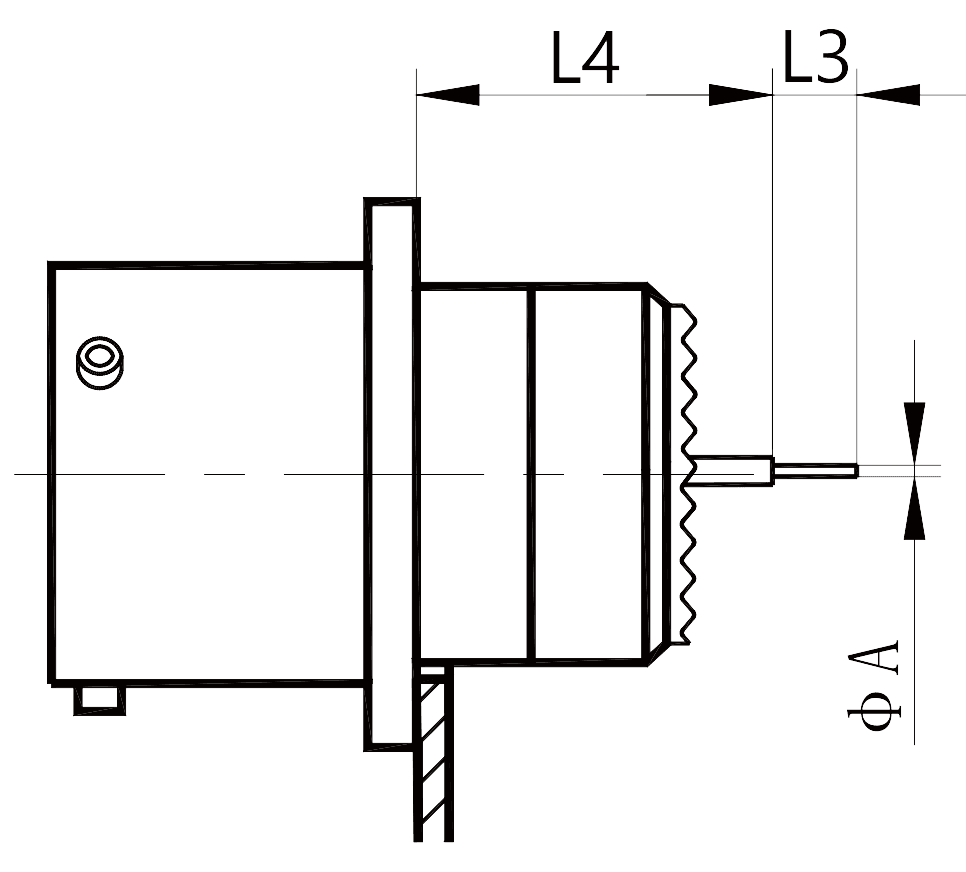
Terminal dimensions
Straight PCB terminal receptacle and terminal tail size
| Type 27468 socket | Type 27466 socket | Type 27656 socket |
 |
 |
 |
| Straight PCB contact terminal specifications | L3 | A | |
| #22D | Long straight PCB terminal contact PL SL | 8.50 | 0.70 |
| Short straight PCB contact terminal PC SC | 4.00 | ||
| #20 | Long straight PCB terminal contact PL SL | 8.50 | 0.70 |
| Short straight PCB contact terminal PC SC | 5.10 | ||
| #16 | Long straight PCB terminal contact PL SL | 8.50 | 1.15 |
| Short straight PCB contact terminal PC SC | 5.10 | ||
| Dimension of contact parts with different specifications | Shell No. 09、11、13、15、17、19 | Shell No. 21、23、25 | ||
| Installed contacts | ||||
| L2 | #22D Pin | Min. | 9.07 | 9.07 |
| Min. | 10.06 | 10.06 | ||
| #22D socket | Min. | 8.74 | 8.74 | |
| Min. | 10.06 | 10.06 | ||
| #20 or #16 Pin, socket | Min. | 9.24 | 9.24 | |
| Min. | 10.23 | 10.23 | ||
| L4 | #22D Pin | Min. | 13.91 | 13.91 |
| Min. | 15.08 | 15.08 | ||
| #22D socket | Min. | 13.58 | 13.58 | |
| Min. | 15.08 | 15.08 | ||
| #20 or #16 Pin, socket | Min. | 14.08 | 14.08 | |
| Min. | 15.25 | 15.25 | ||
| L5 | #22D Pin | Min. | 11.60 | 12.35 |
| Min. | 12.47 | 13.22 | ||
| #22D socket | Min. | 11.27 | 12.02 | |
| Min. | 12.47 | 13.22 | ||
| #20 or #16 pin, socket | Min. | 11.77 | 12.52 | |
| Min. | 12.64 | 13.39 | ||
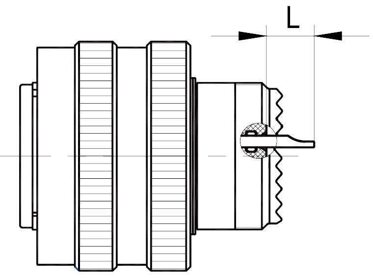
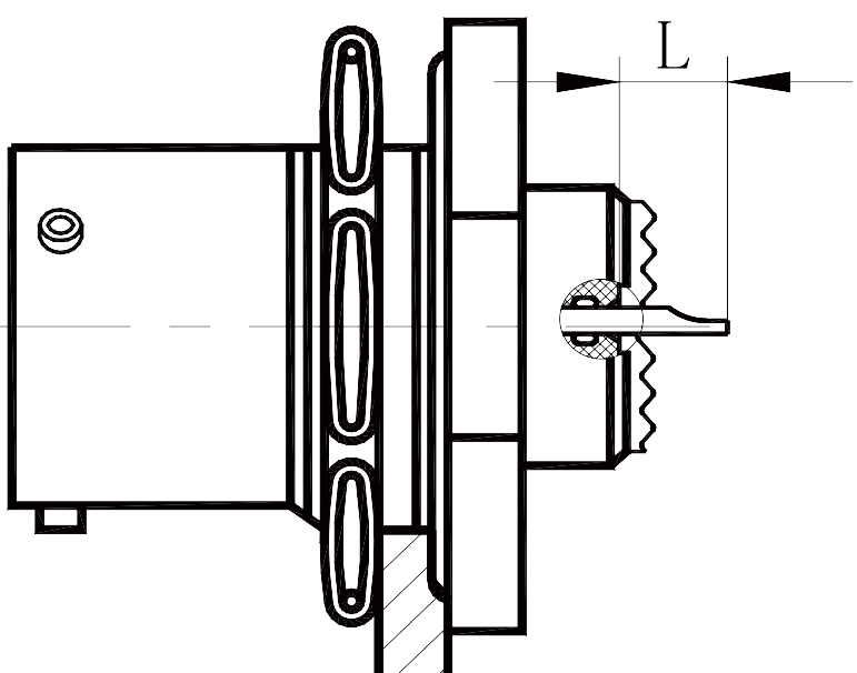
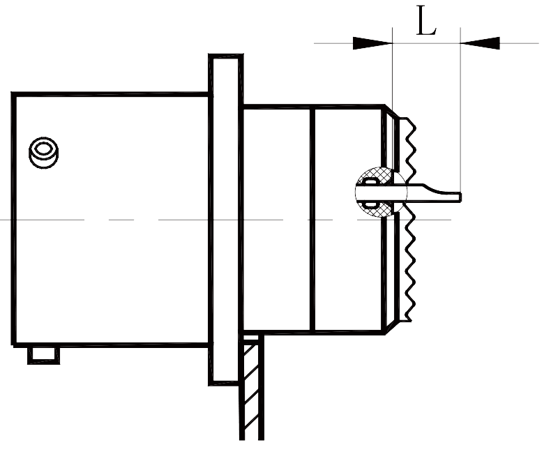
Solder terminal end size
| Type 27466 plug | Type 27468 socket | 27466 type socket | 27656 type socket |
 |
 |
 |
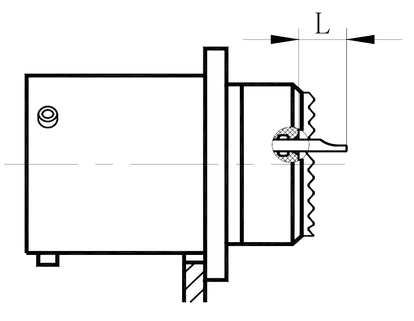 |
| No. of contacts | Contact | L |
| #22D | Pin / Socket | 3.5 |
| #20 | Pin / Socket | 3.5 |
| #16 | Pin / Socket | 4 |
| #12 | Pin / Socket | 4 |
| #8 | Pin / Socket | 9 |
Note: L refers to the distance between the end of the contact cup and the end face of the sealing body.